3D Terms
An Albedo Map is basically an Image texture without any shadows or highlights.
Take the image below as an example. On the left, we have a picture of a brick wall with shadows and highlights and on the right, these shadows and highlights are missing. The image on the right is an Albedo Map.

Side by side comparison of a regular Photo and an Albedo Map.
source
Ambient occlusion is a shading and rendering technique used to calculate how exposed each point in a scene is to ambient lighting. For example, the interior of a tube is typically more occluded (and hence darker) than the exposed outer surfaces, and becomes darker the deeper inside the tube one goes.

Back-face culling determines whether a polygon of a graphical object is drawn. It is a step in the graphical pipeline that tests whether the points in the polygon appear in clockwise or counter-clockwise order when projected onto the screen.
The process makes rendering objects quicker and more efficient by reducing the number of polygons for the program to draw. For example, in a city street scene, there is generally no need to draw the polygons on the sides of the buildings facing away from the camera.

Baking is the name of the process about saving information related to a 3D mesh into a texture file (bitmap). Most of the time this process involve another mesh. In this case the information of the first mesh are transferred onto the second mesh UVs and then saved into a texture.
While some application may support baking information into the mesh properties (such as vertex colors), Substance Bakers only allow to bake information down to a texture. However they can read mesh properties and bake them down to textures (like vertex colors) source

Most often it is used to name the general mathematical function which describes the way in which the light is scattered by a surface. However, in practice, this phenomenon is usually split into the reflected and transmitted components, which are then treated separately as BRDF (bidirectional reflectance distribution function) and BTDF (bidirectional transmittance distribution function). source
Box modeling is a technique in 3D modeling where a primitive shape (such as a box, cylinder, sphere, etc.) is used to make the basic shape of the final model. This basic shape is then used to sculpt out the final model. The process uses a number of repetitive steps to reach the final product, which can lead to a more efficient and more controlled modelling process. source
Bump mapping is a texture mapping technique for simulating bumps and wrinkles on the surface of an object. This is achieved by perturbing the surface normals of the object and using the perturbed normal during lighting calculations. The result is an apparently bumpy surface rather than a smooth surface although the surface of the underlying object is not changed. Bump mapping was introduced by James Blinn in 1978.

Displacement mapping is an alternative computer graphics technique in contrast to bump, normal, and parallax mapping, using a texture or height map to cause an effect where the actual geometric position of points over the textured surface are displaced, often along the local surface normal, according to the value the texture function evaluates to at each point on the surface. It gives surfaces a great sense of depth and detail, permitting in particular self-occlusion, self-shadowing and silhouettes; on the other hand, it is the most costly of this class of techniques owing to the large amount of additional geometry. source
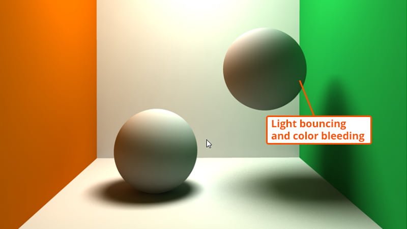
Global illumination (GI), or indirect illumination, is a group of algorithms used that are meant to add more realistic lighting to 3D scenes. Such algorithms take into account not only the light that comes directly from a light source (direct illumination), but also subsequent cases in which light rays from the same source are reflected by other surfaces in the scene, whether reflective or not (indirect illumination). source
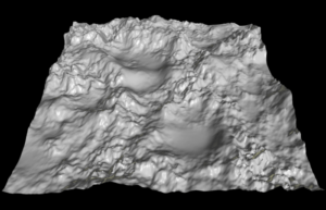
A heightmap or heightfield is a raster image used mainly as Discrete Global Grid in secondary elevation modeling. Each pixel stores values, such as surface elevation data. A heightmap can be used in bump mapping to calculate where this 3D data would create shadow in a material, in displacement mapping to displace the actual geometric position of points over the textured surface, or for terrain where the heightmap is converted into a 3D mesh.

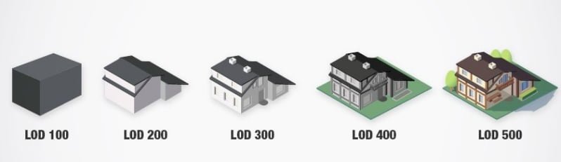
LOD stands for level of detail, and it’s the process of making less detailed versions of your models that are viewed when they’re further away from the camera.
This lowers the strain on the computer allowing it to render more objects while maintaining a high frame rate.
There are generally 2 parts of the model that get optimized for LOD. These are the geometry (polygon count) and the texture resolution (lower resolution textures = smaller file size).
LODs are usually numbered within the real time engine that you use. LOD0 is the full detail model that is viewed closest to the camera. From there LOD1 is a lower detail version, followed by LOD2, etc.
An N-Gon is a polygon with more than four vertices and edges. Due to its geometric properties, an N-Gon can always be divided into quads, tris, or a combination of the two; so they are always easy to remove by adding connecting edges between the border vertices.

In 3D computer graphics, normal mapping, is a texture mapping technique used for faking the lighting of bumps and dents – an implementation of bump mapping. It is used to add details without using more polygons. A common use of this technique is to greatly enhance the appearance and details of a low polygon model by generating a normal map from a high polygon model or height map. source
Non-uniform rational basis spline (NURBS) is a mathematical model using basis splines (B-splines) that is commonly used in computer graphics for representing curves and surfaces. It offers great flexibility and precision for handling both analytic (defined by common mathematical formulae) and modeled shapes. It is a type of curve modeling, as opposed to polygonal modeling or digital sculpting. NURBS curves are commonly used in computer-aided design (CAD), manufacturing (CAM), and engineering (CAE). They are part of numerous industry-wide standards, such as IGES, STEP, ACIS, and PHIGS. source


Parallax mapping (also called offset mapping or virtual displacement mapping) is an enhancement of the bump mapping or normal mapping techniques applied to textures in 3D rendering applications such as video games. To the end user, this means that textures such as stone walls will have more apparent depth and thus greater realism with less of an influence on the performance of the simulation. source
Phong shading, Phong interpolation, or normal-vector interpolation shading is an interpolation technique for surface shading invented by computer graphics pioneer Bui Tuong Phong. Phong shading interpolates surface normals across rasterized polygons and computes pixel colors based on the interpolated normals and a reflection model. Phong shading may also refer to the specific combination of Phong interpolation and the Phong reflection model.

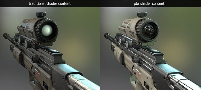
Physically based rendering (PBR) is a computer graphics approach that seeks to render images in a way that models the flow of light in the real world. Many PBR pipelines aim to achieve photorealism. Feasible and quick approximations of the bidirectional reflectance distribution function and rendering equation are of mathematical importance in this field. Photogrammetry may be used to help discover and encode accurate optical properties of materials. Shaders may be used to implement PBR principles. source
PBR is a way game developers can simulate the interplay between materials and light in a way that simulates reality. It is the combination of these two technologies in a real time gaming environment that make it possible for developers to deliver high quality realistic imagery.
The number of faces your object is made of. If the model is constructed of quads, those should be used to calculate the number. Otherwise, tris can be used. If a 3D model has a large polycount, it can cause your computer to lag, depending on your specifications. source
In computer graphics, a procedural texture is a texture created using a mathematical description (i.e. an algorithm) rather than directly stored data. The advantage of this approach is low storage cost, unlimited texture resolution and easy texture mapping. These kinds of textures are often used to model surface or volumetric representations of natural elements such as wood, marble, granite, metal, stone, and others. source
A square or rectangular polygon is referred to as a quad or quadrilateral polygon, and is a four-sided polygon. It has exactly 4 vertices at the corners connected by 4 edges. This is the most desired type of polygon when creating digital models, and many artists like to build their objects using nothing but quads to help make their work more appealing to customers in complex pipelines.

Ray tracing is a rendering technique that can realistically simulate the lighting of a scene and its objects by rendering physically accurate reflections, refractions, shadows, and indirect lighting. Ray tracing generates computer graphics images by tracing the path of light from the view camera (which determines your view into the scene), through the 2D viewing plane (pixel plane), out into the 3D scene, and back to the light sources. As it traverses the scene, the light may reflect from one object to another (causing reflections), be blocked by objects (causing shadows), or pass through transparent or semi-transparent objects (causing refractions). All of these interactions are combined to produce the final color and illumination of a pixel that is then displayed on the screen.

The process of converting 3D models into 2D images. Rendering can create one image, a sequence of images that you can stitch together, or a video. You’re able to view the quality of the 3D model through multiple rendered images on the model page. source
Rendering or image synthesis is the process of generating a photorealistic or non-photorealistic image from a 2D or 3D model by means of a computer program. The resulting image is referred to as the render. source
The 3D model has a skeleton so it can move. You can deform and animate characters, vehicles, and other objects using rigs. This allows you to animate the 3D model. source
An SBS file contains a substance package created by Allegorithmic Substance Designer (Adobe Substance Painter), a program used to create materials for use in 3D content, such as animations, special effects, and video games. It stores a graph with nodes that visually represent the properties of the 3D material. SBS files also include all the resources that make up the 3D material. source
An SBSAR file is an archive created by Allegorithmic Substance Designer (Adobe Substance Designer), a program used to create materials for use in 3D content, such as animations, special effects, and video games. It contains a 3D material, such as concrete, carpet, glass, marble, steel, slate, iron, metal, wood, and glass. SBSAR files are used to share materials that have been made by Substance users or are available for download with a Substance Source subscription. source
Shading refers to the depiction of depth perception in 3D models or illustrations (in visual art) by varying the level of darkness. Shading tries to approximate local behavior of light on the object\'s surface and is not to be confused with techniques of adding shadows, such as shadow mapping or shadow volumes, which fall under global behavior of light. source
In computer graphics, tessellation refers to the dividing of datasets of polygons (sometimes called vertex sets) presenting objects in a scene into suitable structures for rendering. Especially for real-time rendering, data is tessellated into triangles.

Surface texture on the model that involves using two-dimensional digital image files, such as .jpegs or .pngs. source
A 3D model’s edge distribution and structure. Good topology is important for displaying materials/textures properly and being able to deform models properly for animation. source
Short for "triangles". A triangular polygon is referred to as a tri or triangle, and is a simple three-sided polygon. It has exactly 3 vertices at its corners and 3 edges connecting those points. This is the smallest configuration required to make a polygonal face.

UV mapping is the 3D modeling process of projecting a 3D model's surface to a 2D image for texture mapping. The letters "U" and "V" denote the axes of the 2D texture because "X", "Y", and "Z" are already used to denote the axes of the 3D object in model space, while "W" (in addition to XYZ) is used in calculating quaternion rotations, a common operation in computer graphics. source

A vertex is a point placed in the space. More than one vertex are called vertices. With a 3D cube, for example, the vertices correspond to the corners. They define the shape.
- Linking 3 or more vertices together creates a face.
- Linking 3 vertices creates a triangle.
- Linking 4 vertices creates a quad. Linking more than 4 vertices creates a polygon.
